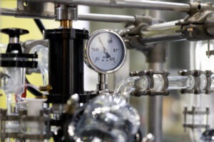
A pressure gauge is a device that is used to measure the intensity of the fluid. Pressure gauges are needed for the arrangement as well as regulation of fluid power machines and are crucial in correcting or balancing them. In this article, we shall discuss the Hydraulic pressure gauge in detail.
Without the help of pressure gauges, fluid power systems would be both uncertain and undependable. Gauges help to make sure that no leaks or pressure changes are present that could influence the working condition of the system which may be hydraulic.
Table of Contents
What Is A Hydraulic Pressure Gauge?
The hydraulic pressure gauge works in a proper range of pressures so that the gauge could be rated for that particular range. These days, hydraulic pressure gauges are accessible to measure up to 10,000 psi, however, at most, the hydraulic pressure can be typically in the 3,000 to 5,000 psi range.

Hydraulic gauges are usually installed at or near the pressure of the pump port for indication of the pressure of the system, but we can install them anywhere on the machine at places where the pressure needs to be observed—especially if sub-circuits work at a pressure rate which is different from pump pressure, such as after a reducing valve. Often, pressure-reducing valves have a gauge port to tap into which allows you to directly monitor the setting of the downstream pressure.
Measurement Of Pressure Using A Hydraulic Pressure Gauge
Measurement of pressure can be done in three ways—absolute, gauge, and vacuum. A measure of actual pressure which includes even the ambient air is zero-referenced with a perfect vacuum, but can be as high as 14.7 psi at sea level is known as absolute pressure. Absolute pressure readings are treated as very important in applications interacting with ambient air, such as the calculation of compression ratio for the flow (cfm) requirements.
A zero-referenced pressure against ambient pressure is known as gauge pressure. It is being used in most applications working in, but not with, ambient air, such as in fluid power systems. When it gets disconnected from the equipment, gauge pressure will automatically fall to zero.
The final form of pressure, vacuum pressure is represented in Torr, or referenced against ambient pressure, as with “in.-Hg” (inches of mercury) units, which is used for the measurement of pressure below ambient.

Working Of Hydraulic Pressure Gauge
The hydraulic pressure gauge uses a simple principle that a flattened tube tends to get straightened or regain its circular form in cross-section when gets pressurized.
However this change in the cross-section cannot be noticed easily, and thus involving little more stresses within the elastic range of easily workable materials, the strain of the material of the tube is increased by forming the tube into the shape of the C letter or even a helix, such that the entire tube tends to either straighten out or uncoil, elastically, as it receives pressure.
In actuality, a flattened thin wall, the closed-end tube is connected at the end which is hollow to a fixed pipe containing the fluid pressure to be measured. As the pressure gets increased, the closed-end moves in an arc, and this motion is converted into the rotation of a (segment of a) gear by a connecting link that is usually adjustable.
There is a small-diameter pinion gear on the pointer shaft, so the motion is magnified further by the gear ratio. The indicator card is positioned behind the pointer, and the beginning pointer shaft position, the linkage length, and the initial position, all give the means to calibrate the pointer to indicate the desired range of pressure for variations in the behavior of the tube itself.
Differential pressure can be measured by gauges containing two different tubes, with connecting linkages.
Different Styles Of Hydraulic Pressure Gauge
They are many types styles of hydraulic gauges, the most common among which are Bourdon tubes and below gauges. Bourdon tubes work by considering the pressure and converting it into mechanical energy. This energy then works by moving a dial in the gauge which displays the current amount of pressure in the system. Bourdon tube gauges are these days one of the most commonly used gauges and may have different configurations such as curved, helical, and spiral. The pressure range decides the style of the tubing, the size of the tube, and the material to make it out from. One crucial thing to notice is that the cross-section of the tubing changes with increasing pressure, which is an important property. Usually, as the working pressure of the gauge gets increased, the shape of the cross-section of the design of the tube will slowly change from an oval shape to a circular shape.

The working of the bourdon tubes is very simple. They consist of a semicircular and flat tube made up of metal, fixed at one end and attached to a sensitive lever mechanism at the other end. The force of the fluid attempts to straighten out the curved tube with an increase in the pressure inside the tube. The tube then gets pulled away from the lever, which because of being connected to the needle on the display, shows the pressure at the fluid port.
Although bellow gauges function almost similar to Bourdon tubes, they are still different in the fact that they use a spring to estimate the quantity of energy to push the dial. The spring is expanded as well as compressed by the pressure present in the tubes and the energy that is created by the motion gets transferred into gears that in turn move the pressure dial.
1. What Is The Purpose Of A Pressure Gauge?
2. Where should a Hydraulic Pressure Gauge Be Installed?
3. How does a Hydraulic Gauge Work?
Conclusion:
Needed to use for testing equipment or operating some machinery, the right pressure gauge helps to reduce the expenses as well as the management of time. In mechanical applications involving hydraulic systems, the common threats to the reliability of the gauge are vibration, pulsation, and pressure spikes.
Thus, it is always best to look for gauges designed specifically for hydraulic applications.
I hope it helps!


